OUR SUPPORT
XTX Zero 16
Wiring Guidelines

The
XTX Zero 16
has 16 digital inputs giving it the ability to monitor up to 16 machines.
Input Connections
Each XTX module uses three input connections. A 24V DC power supply, a network connection to your LAN and a cycle signal from your machines.


Power
A 24-volt, 18-watt DC power supply is needed at the location of each XTX module. Whilst each module is protected by an internal 1.5A resettable fuse, an in-line fuse should be provided to protect the wiring against over-voltage, protecting the module.

LAN
A network connection is needed to connect the XTX module to our cloud service using a standard RJ45 connector.

Network Test
The connection status can be checked by navigating to https://status.intouchi4.com/
If any of the tests show up in red, access to our services may be blocked and will need to be rectified with your IT department.

Cycle
The XTX module requires a cycle signal from each machine provided by either an open, volt-free contact relay, or a solid-state relay using any two-core cable that is capable of carrying 20 milliamps or more.
For discreet processes, such as injection moulding or metal stamping, the relay should be controlled by a signal which activates once during each machine cycle.

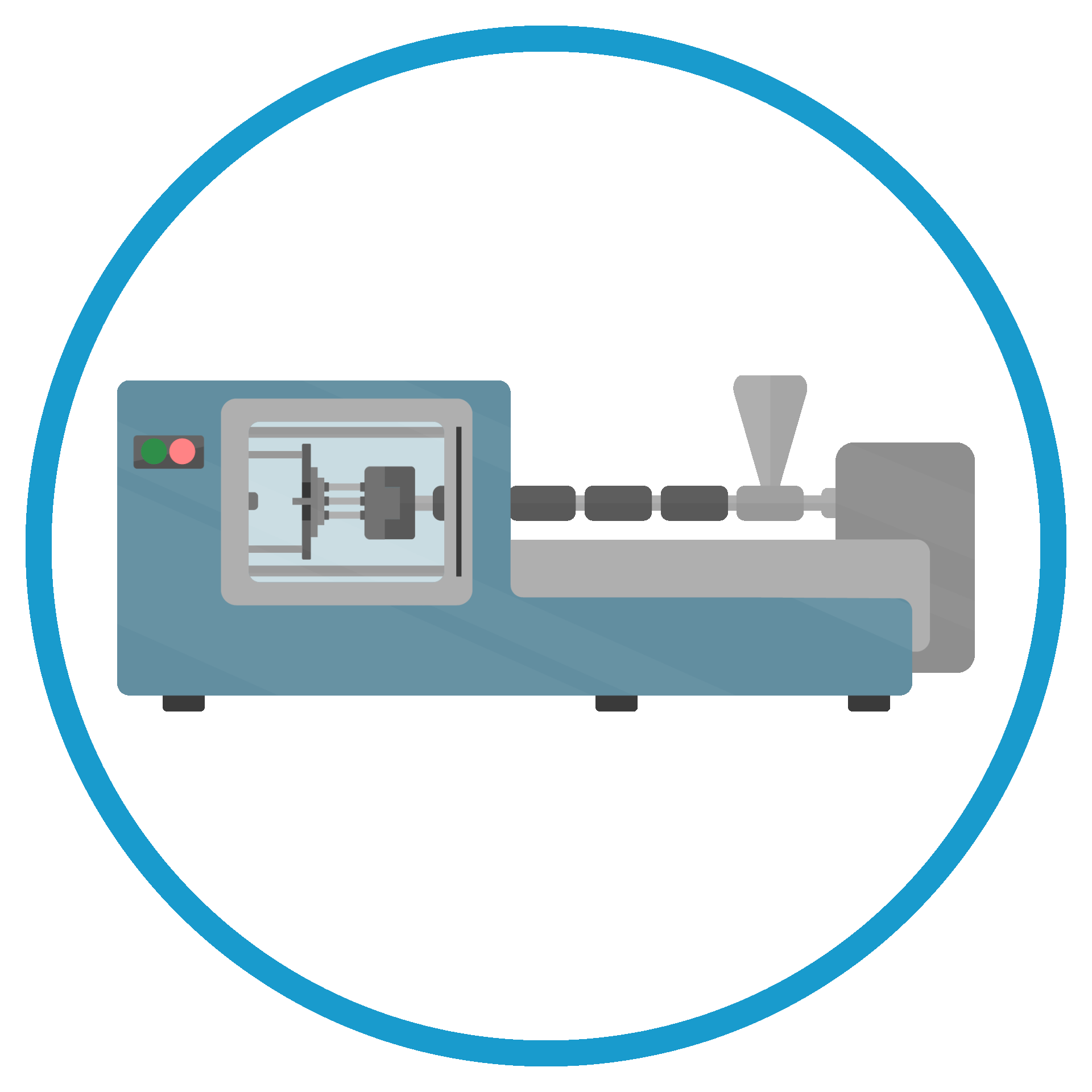
For continuous processes, such as extrusion, the relay should be controlled by an output from a rotary encoder. A solid state relay (SSR) is recommended, and essential for very fast signals.

On the front side of the XTX module, you will find a series of connectors and ports. Starting from the left you will see the RJ45 port to insert your ethernet cable in to. Over to the right slightly, you will find a 7-pin connector – This is where the 24V power supply cables go into.

To the right of these are 4 sets of 5 pin connectors – these are the inputs from each machine.
Let's take a look at the set up as a whole

Each time the machine cycles, the relay will close the circuit and activate a light on top of the XTX module, verifying that the circuit is working.

Our cloud software monitors these signals to find the cycle time, active time and trailing time, allowing you to monitor the output of your machines in real-time.
Need help?
View our videos, guides and walkthroughs on how to optimise your Intouch monitoring solution.
Alternatively get in touch with our expert support team.